serving hattiesburg and the surrounding area.
(columbia, petal, purvis, sumrall, laurel, USM, jcjc, jones county, lamar county, forrest county)
serving hattiesburg and the surrounding area.
(columbia, petal, purvis, sumrall, laurel, USM, jcjc, jones county, lamar county, forrest county)
helped a friend out the other day with one of those problem jobs that had just kind of beat them up and rather than heap an additional expense by charging him for what i had helped them with, i asked him about this subwoofer (polk audio psw125) he had in the corner (for the last YEAR!).

he said it was having some issues, and would need a new board (supposedly around $80) but would let me have it in trade. the thing retails for ~$300 and i felt it would be a good opportunity IF… i could fix it. i had put about 2.5 hours into his problem, but if felt like a good vegas bet – and he wasn’t doing anything with it – plus i LOVE bass. so i threw it in the car and lugged it home. the speaker worked great, but wasn’t too long that i found the issue. at first i thought that someone was beating something in the distance. a regular consistent thump. then i got closer, put my ear up to the speaker and found that my newly acquired speaker had a heartbeat! wasn’t very loud, just annoying. i could see why someone would have unloaded it. many subwoofers are “always on” with an on, or auto setting – so unless i was willing to find a convenient way to “unplug” it, this would need to be fixed.
so the fixer in me began to research what the problem could be. what i found was that many people with similar issues had pointed a finger at a couple of capacitors located on the motherboard. that polk had maybe came too close to the line with their specifications. that actually some people recommended upping the voltage, while maintaining the capacitance.
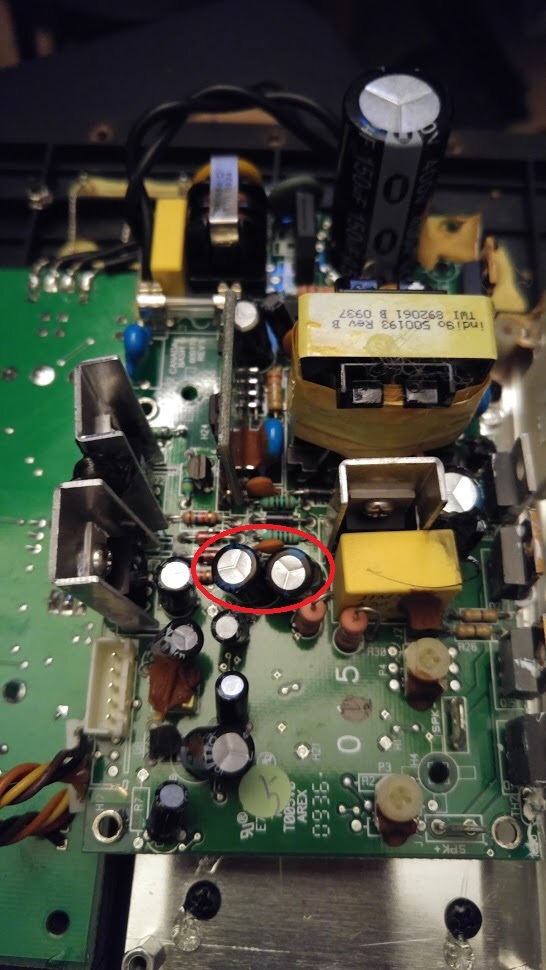
the posts said the problem was 2 capacitors 63v 47uF cd268 105°C. found the datasheet also. that the capacitors were beginning to fail. that they were charging/discharging and that was the reason for the heartbeat. i actually learned that capacitors have a lifespan that is directly related to temperature. and that some capacitors were rated at 85°, others at 105°.
i went to digikey and did some searching and ended up deciding on these. these had a 5000 hour lifetime @105° as opposed to the original which was rated for 2000 hours. also learned something else. that there were different ripple rates. and that the higher the ripple, the higher the heat. the newer capacitors from panasonic had a lower ripple rate of 80mA as opposed to the original ones which were 90mA. so all in all, the newer capacitors should have a longer shelf/working (load) life that the original ones.
i also decided to replace all the other ones while i was at it.
you can find the links to them at digikey here: 1, 2, 3, 4, 5, 6
to get to the underside of the capacitors to remove them, i needed to remove some screws that have been sealed with some type of loctite. the heatsink will need some thermal paste reapplied when reassembling it. these capacitors are polarized, so orientation is important.
all in all, i think it was a good trade. glad to help a friend and put a great sounding subwoofer back into service.
update:
it’s been awhile since i posted this, so i have mentally moved on to other projects. i have been getting some interest on this post from other people and maybe someone that is currently moving through the project can add a comment to clarify. i’m so glad this post has helped others. i really like this speaker and if we can help to keep them going that’s even better. i’m not going to turn off commenting, but don’t intend to personally answer any future questions on this particular post.
i also located a youtube video from a polk blog post.

Thanks for this was able to repair mine also.
Thanks for the tips and pictures, replaced the two defective capacitors and it works save me a few hundred bucks thanks again
so glad – thanks for the kind words.
Amazing – thank you! I will print this out and go from here. I have TWO subs with identical problems.
that “heartbeat” and smoothing capacitors… who knew. a great audio example of what they do.
How do you see the capacitors are failing? Those on my board measure within 20% of the nominal capacity. (I checked five the biggest.)
apparently if you are hearing the pulse – it’s going to be the capacitors. this device is default always on, so with the age of this device, the caps just wear out – and it’s an easy, cheap solution. you haven’t really lost anything by trying. the wear may not be visible (exploding, bursting), but the pulse indicates that they are not “smoothing” anymore.
Thank You mr. fxr!
My problem may be different, as it’s not exactly a heartbeat, but rather a constant noise, like a humming, whenever the device is powered on, with or without the signal. It appears from the replies that some people fixed it as well with the capacitors replacement. And some people mentioned replacing a JFET transistor. I measured the capacitors, and since they looked healthy, I looked at the JFET. This appeared faulty, showing constant low resistance between source and drain. I ordered replacement JFET, but both new items I received measure the same as my old one. May be a coincidence, of course. So I’m seeking additional advice here before ordering more parts.
Did you ever figure out the repair? I have the constant hum too. Looking in to fixing it myself. Green light is on. Sub constantly hums but wont play any audio..
Can you provide a link to this JFET transistor? I’ve been searching around online and I cannot find a part number. Thanks!
Any codes for the jfets. Noone seems to know what they are except they begin with tip3???
The Jfet code is J113, but for understand if could be the cause, you can tray just give out it, it make a only mute audio funtion when sub is in standby. After you can replace it, if is the cause.
Question, I bought all the capacitors through digikey and soldered the new capacitors in but ran into and issue with the two small capacitors near the hand marked 5 on the yellow round paper sticky. They are both labeled 35V 4.7UF. After taking off the first one I noticed no polarity mark on the capacitor or on the board (different from all the others). I took a chance putting in the new capacitor by guessing the polarity position of the new capacitor installation by looking on the reverse and positioning the negative based on the connecting device being similar to another capacitor layout and connection. I did not remove the other non polarity labeled 35V 4.7UF capacitor located at the very bottom of the earlier photo. Fortunately installed the board and the subwoofer now sounds like when new, (no heartbeat, no crackling). Might have gotten the polarity correct. Question is how do you tell the polarity for these two capacitors, or does it matter for these two?
it’s been awhile since i posted this, so i have mentally moved on to other projects. i have been getting some interest on this post from other people and maybe someone that is currently moving through the project can add a comment to clarify for us. i’m so glad it helped. i really like this speaker and if we can help to keep them going that’s even better. thanks for your comment.
Mine sounds distorted and clipped at low volumes but is fine when cranked. This sounds like a transistor problem?
There are two capacitor not polarized couse they are on the input of power stage. Is better to use not polarized couse they are in the pat of signal. Anyway they are not stressed and rarely will cause of problems, I think replacing is no needed
Which thermal paste did you use from Digi-Key?
i have my own. i’m not sure i ordered any from digi-key yet. btw – did you know that autozone offers a cheap thermal paste? not very well known, but could come in handy to know in a pinch. autozone item #SL203 here is a link https://www.autozone.com/miscellaneous-cleaners-and-degreasers/heat-sink-compound/wells-heat-sink-compound-1-ea/19189_0_0
I decided to try and replace the 2 capacitors pictured in this post with the exact model that you chose. The replacement went pretty smoothly and when I plugged everything back I see the Green LED light up and no more heartbeat. I was getting excited but then when I tried playing music, I still get no bass =( and to top it off the thing started SMOKING after a couple minutes LOL. I immediately unplugged it and accepted defeat. Is my only solution to replace the whole amp now or are there more things I can test?
ouch… if you had the magic smoke, sounds like something got grounded during your process. if you can pinpoint where the magic smoke came from and want to try again, it’s possible you may have some success, but it’s a risk. the capacitors are not that expensive, so it’s possibly it may be worth it to try. but the entire board may also be available for purchase as well. but this is an older device, so eventually the only solution would be to repair.
Can you indicate how my do I need to order for each of the capacitors 1 to 6. Hard to figure out the numbers on the board without removing the capacitors.
part of the repair is to remove the capacitors – it will have to be done anyway, so pull your capacitors, make sure to note the correct orientation, match the specs and place your order.
First off, thanks so much for this info. Would’ve never bitten off this project had it not been for this post.
The good news: replaced the 2 63V capacitors and it resolved the hissing/humming behavior I observed before repair.
Sub powers on, when active LFE cable is plugged in, standby mode the LED indicator switches from amber to green. Good.
Now for the bad news: no sound whatsoever, from LFE nor speaker terminals. Seems the input is still not working. What should I try next? Replace JFET? Any points I should test on either board with my multimeter to triage?
I’ve also tried this fix, all caps replaced. Light is on and green but as Luke above experienced – no sound. Do any of you have a link to this magic JFET?
I have this subwoofer, and I had this same noise symptom!
I just recapped all electrolytic capacitors for the same value from Nichicon, and ….. another problem arose when connecting the subwoofer.
It emits a “pop … pop …. pop”, and the led flashes at each pop, regardless of the position of the “Standby, Auto or On” switch!
Does anyone have any idea what else could be going on?
Regards!
Rdorigo
Have you ever figured it out? I ended up with the same problem when I replaced the capacitors.
Thanks! This fixed my sub, by just replacing the two mentioned capacitors. I found it difficult to desolder the caps but this was also my first soldering project. I’d say it’s a starter project difficulty level.
that’s awesome! thanks for letting us know! it’s great that you tackled soldering! if you need any pointers on flux or solder, can send me an inbox – sometimes it really matters. i started trying to use my dad’s stuff and it just wasn’t cutting it. once i got the correct stuff – things fell into place.
Can anyone point me in the right direction for the JFET transistor please? Thanks!!
Awesome, I’ve been able to fix my sub! Thanks for the helpful information.
Thank you so much! Works great. As an aside. I was I bit stymied by how the head sink holders when back on. I forgot to take a picture before disassembling. I was thinking the holders would grip on the transistor heat sinks, not the transistor bodies.
Thank you very much! Fantastic solution, helped me revive my woofer.
so glad – thanks for the feedback!
Another successful repair here! Thank you very much!
awesome – thanks for the feedback!
Thanks for the input. Have a Polk PSW 111 with static and a heartbeat when the power cord is plugged in. I will try the repair myself, but can anyone send me the schematics mentioned in the repair articles. I have had this sub for several +++ years and it, just in the last 2 months, started with the static that has now added the heartbeat tone. I was going to recycle it but stumbled on these dyi articles. I grew up building and troubleshooting HealthKit electronics, so I hope that I still have the skills required. Thanks to everyone involved. It should be a fun project.
i think schematics may be limited to certain forums. may be best to post there and respond here with a link.
I did this fix yesterday and popping is gone. I do wonder if the quality of the caps I purchased from Jaycar in Australia has any impact on the sound, but it was a $1.50 in total. Owner sold it to me saying his caps had blown in the past. I could see one bulged and it was not one of the two in the video, but the same spec 63v 47uF 0.3 edf. So i went ahead and replaced all three and replaced he thermal compound with non conductive pc paste. I don’t have any electronics to test caps and sort through. Its fix and im happy. Thank to the poster.
Thank you!! mine was doing same. annoying light heartbeat. Polk said discontinued and no parts so $400. So i ordered 2 capacitors you put links to and boom. fixed like new! Thing i’d add for anyone new to this stuff is remember capacitors are + and – so make sure positive is on the square solder hole and negative on round. and also get a cheap “solder sucker” to suck out solder when heated. Once opened and found the solder points it took me like 10mins to fix. Your article saved me around $400 for $2 in parts.
wow – that’s so great to hear – thanks for the feedback!
Hi you there!
I am from Brazil and have one PSW110 with a blowed Q8.
Does anyone knows what transistor is that?
With thanks in anticipation,